Hello,
i have search the schematic of the board and i’m a bit confused.
Power input of the board from USB OTG it’s the same of GPIO pins 2 and 4?
Can i use GPIO 2 and 4 pins to power external peripherals like hub USB?
Can i power the board through USB HOST?
Whats the maximum power output from USB HOST? It seems if i connect something power hungry to USB HOST ~1A, the voltage drops to ~4.2V and the board become very slow and instable in the wifi connection.
Radxa Zero Power input/output
I think they are both directly connected to your power supply
Yes but I don’t have the gerber file to confirm how they are connected. It might be a thin trace so I’d advise against using high power devices on GPIO as a precaution.
That’s not possible. AO_5V and AO_5V_B are connected by a SY6280AAC switch on page 8. The switch will block reverse current.
From the schematic it is set at 1.4A. If you are having voltage drop issue you might want to check with your power supply as well.
Thanks for the reply, but i need to confirm all these power connections because i want to develop my hardware projects and don’t want to damage this expensive board…
Um just create a separate power circuit to power both Zero and your additional hardware. and only connect signal to Zero? I don’t know why you are so determined to use Zero to power high load devices. That’s not the intended purpose.
hello,
i have made a power circuit for my project and i see that the power connectors have a drop of ~0.2v at 1.3A of load in the batterys… it’s a lot!!
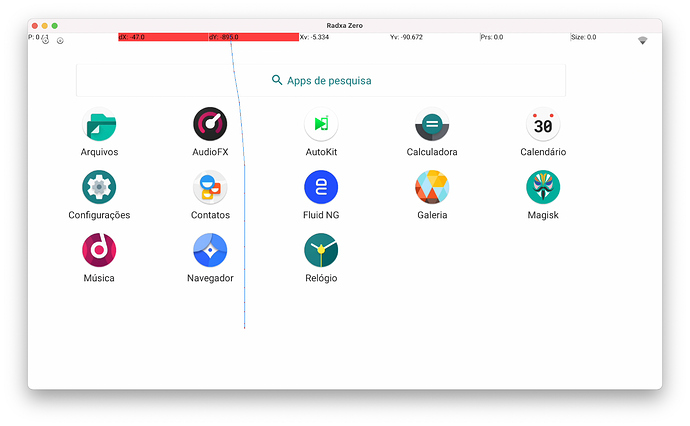
At next review of the project i will fix this. Now i need to solve the software issues because the Android version that i have is an ATV customisation and don’t have support for touch…IMG_20211230_091223|690x388
ATV is not made to work with touch, you need to use either Linux or Android non-tv.
I choose the last one and builded the image, I can provide the steps if you want to compile by yourself but you need minimal skills with Linux to compile it.
it would be great if you provide the steps.
linux skils… i will ask google or you for a little help 
the print that you make is from Android Official? I don’t see there the softkeys in the screen to navigate with touchscreen…
You can control almost everything with the touch screen and in the rare cases you can’t, I’m using Fluid NG to have gestures for the “back button” and the “home button”.
I will compile the instructions and post later today.
I tried to have the soft buttons but I’m not sure has it natively or what, long time I don’t work with Android, but Fluid NG filled the gap.
If we use the GPIO to power the board, could we use the USB OTG for something like one of these?
https://smile.amazon.co.uk/dp/B09CYCGRR2
https://smile.amazon.co.uk/dp/B07DVCVVZG/
I mean, I would guess that there’s still no USB3, but that’s OK as the connections will just work at 2.0. I plan to use this all with the MEGA PI case, and if it passes through enough power to the RADXA ZERO I think it could be an amazing option. As I would be able to place a USB-C hub with ethernet on the main port, and BOOM. 
Anyway, I guess what I’m asking is … If I use GPIO 2 will it provide as much power to the board as the USB-C input?
EDIT - It’s a week later … and … well … I’m powering my board using the RetroFlag Mega-Pi case, currently, and it played back a hard file over a USB GB ethernet connection on a powered USB hub in the main USB-C port, with a simple OTG cable connecting a wireless keyboard in the power port. So it looks good!
Interesting, I was also looking into how we can use both USB ports for peripherals. So far I was able to power the Zero via GPIO pins 2 and 6. And connecting a USB C hub on the OTG port did not work, I’ve connected a wireless keyboard on the Hub to test this.
Did you do anything different to get it to work @eliotcole
What version of android have you built?
hi, can you provide link for the otg cable you are using? thanks
Is this true for the Zero 3E as well? I plan on using the Radxa Zero 3E for a project, that needs a good amount of power output on the USB 3.0 host port.
They are different products with different schematics, but it is also 1.4A.
