Let's build a laptop

A cable like this might be useful, but not sure whether this cable expose all pins to work with DP.

And in my case, i prefer not exposing something externally since if the board is fitted into a case / enclosure it might not be a good idea to have to plug something outside the enclosure. I would prefer to have everything inside the enclosure.

Not sure either, might give a try to see if it works
I’m also looking for a way to upgrade my board with UPS. I’m thinking leaving it in its original case (when i receive one) and plug custom UPS outside the case through usb-c

1 Like

What UPS / Power module are you planning to use? Since i am also looking for a ups / module for my rock 5B as an NAS + Router.

Haven’t looked that much yet, (so many things to look for that board: case, wifi card, 4G module, powering), but bit by bit getting there …
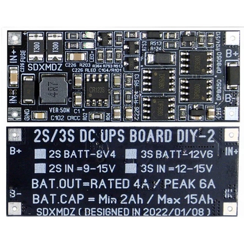
Probably something similar to what the author posted with 18650 cells.
First I thought plugin it on GPIO but seems like we can’t go up 5V and power might be limited that way… So might go for the usb-c hack we discussed.

Also looking to make it a router with 4G, plus all purpose server :slight_smile:

1 Like

That one actually looks pretty good to me especially the 12V model as that UPS support automatic charging and powering seamlessly on the same port without requiring an external power source. However, if it can only handle 15W, it would not be sufficient for our rock 5B especially if u have an nvme ssd, or other pcie devices. And worth noting that the module seems to be a boost module, the 18650s are in parallel (3.7-4.2V).

I think that if there is a module which use a buck converter, it would usually handle more power, and this will allow the use of more cells in series.

Since our rock 5B is a larger form factor board than a raspberry pi, it might also be worth considering using 21700 cells for larger capacity.

1 Like

The module mentioned on the first post seems only support 5V input for charging, but the usb-c pd will most likely activate the max voltage on the rock 5B which means the module will not be suitable.

I found a module that output the battery voltage instead of using a buck or boost module, it can output upto 50W, it runs 3S battery. However, it seems only support input upto 15V. If the rock 5B negotiates a PD 20V, it might be possible that it can break the ups module.

Using buck would decrease output voltage meaning you’ll need to put cells in series and you’ll also need to have BMS to balance charge.
In PD power bank, they usually put 2 big batteries in parallel, though they are often limited to 18W.

The module mentioned on the first post seems only support 5V input for charging, .

I guess this is expected voltage to charge 1S li-on batteries.

but the usb-c pd will most likely activate the max voltage on the rock 5B which means the module will not be suitable

quoting product page:

When the power supply is powered, the power supply directly supplies power to the load through the boost circuit, while charging the lithium battery. Once the power supply is cut off, the battery path is automatically started to supply power to the load through the boost circuit.

In both cases boost is used to scale voltage either from 5v ( if powered) or batterie voltage (around 3.7V), why do you see it as an issue?

The only downside I see is somewhat limited 15W output power but it shouldn’t be hard to find something delivering more power through boost converter. In e-cig it can go above 80W on single cell.

I found a module that output the battery voltage instead of using a buck or boost module, it can output upto 50W, it runs 3S battery. However, it seems only support input upto 15V. If the rock 5B negotiates a PD 20V, it might be possible that it can break the ups module.

That will be for sure more efficient not to use buck/boost, but voltage would be more around 9V at low charge and 12V a full charge? Usually PD only allows certain voltage to be negotiated, in that case I would presume it won"'t allow rock5B to negotiate 20V?

When charging the battery, a buck module is needed to step down the PD’s 5-20V into 5V, the module only accepts 5V input max

you mean at the input of UPS? my understanding is that it would work as follow:

  • plugged in:
    5V DC input => TP4056 Lithium Battery Charger Module => Lion battery => Boost converter => 12V PD output
  • unplugged:
    Lion battery => Boost converter => 12V PD output

I don’t think there is any PD involved in input, just regular DC voltage as per description:

USB port and standard 5V+and 5V - are external power supply ports. You can choose one of them

You can either plug regular usb cable (no PD) which is 5V by default, or plug 5V DC on + - terminal.
My guess is that 15W limitations either comes from USB power supply input not able to deliver more than 3A and/or boost converter not able to handle higher current

Wow, great community! Thanks! Sad I’m not good enough to understand everything, but I got new ideas from the replies. I don’t feel confident to solder on the chip yet.

So if I buy:

One female (for usb-c monitor/power), and three male connector.

Also:

Power bank with two usb-c ports (both bi-direction).

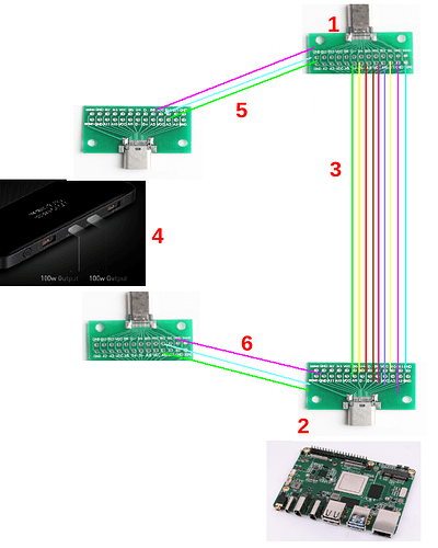
And make magic usb-c cable with power bank in between (I guess that’s what you suggested, but trying to make sure I understand correctly):
1 ) Usb-c female, to connect external power, usb-c monitor, or anything else
2-3) Most of the wires go straight to Rock 5, as it would with regular cable.
4) In between I put power bank with two usb-c PD ports, one port from female/monitor, another port to Rock5
5-6) only “power-related” wires go to power bank.

I’m not familiar with usb-c pd powering protocol yet and how all those wires work, but if someone can agree that theoretically it would work, I will study it.

Thank you all for your help!

Well i mean,

The rock 5B usb-c should input PD 20V when plugged in, for example if the device is plugged to a USB-C monitor with DP and PD 60W. In that case, the ups should be in charging mode to the battery, and the ups will not output any power to the rock 5B. However, the ups charging input seems wants no more than 5V input, which means when a usb-c monitor is plugged in, 20V is supplied to rock 5B which the rock 5B will work normally, however, the ups board’s charging ic may be broke when 20V is supplied.

If you are using the board i suggested on this post

It will be possible to have pd input upto 15V (which means u have to aware of whether your power supply support 20V, if it support 20V, it might not be a good idea using it, or you might have to modify the u-boot / kernel to disable 20V negotiation.

1 Like

I am actually thinking of supplying the ups battery output using the PoE power 5V pin as one of the solution to this 20V PD issue.

However, in this case, we need a module that converts our battery to something around 5V 8A output.

And I have a question on the 5V pin, when the Rock 5B is powered by 5V using GPIO or the PoE, does the usb-c port output 5V power?

Since I see that the usb-c vin goes to the mp8759 and negotiate with the pd controller to allow dynamic input from 5-24V, if the rock 5B is powered using gpio or poe, we are powering everything upto the 5V net, but i am not sure what will the USB-VIN behave in this case when a usb device is plugged into the usb-c port.

ah yes I didn’t consider power coming from screen itself, this will be an issue indeed

Didn’t dig much into rock5b powering topic, so I’ll be of little help here but would be interested if you get more info on that.

Have you considered PD trigger board? I’ve got two of them, I know at least one is able to passthrough video signal while forcing a predefined PD setting (like 15V).

Otherwise yesterday was experimenting/hacking things out of curiosity but now realizing it won’t be appropriate here (due to external screen PD power).

PD power supply => 20V PD trigger => 3S charger => 3S Li-ion + BMS => PD car adapter => USB-C breakout board

with both screen and rock5b connected to usb-c breakout board

The PD car adapter accepts 12-24V DC input and is able to deliver PD output with enough power to rock5B. While working well with only rock5b connected this probably wont be doable with another PD device in the loop…

Finally this UPS topic requires more reflection that I though…

However this seems like what the first post aims to achieve.

It would be perfect if somebody could do a test (simply if somebody is using a poe or a 5V power supply from the gpio, he/she may be able to plug a normal usb drive to the usb-c port to see whether it works or not), I don’t currently own a usb to pin header power cable, so i couldnt test that out at the moment.

I got two of them (one is lost, another one is used to trigger 12V direct input to the rock 5B’s usb-c port as a solution to boot loop / armbian kernel that does not support pd.

Tho u can use a pd trigger board on the usb-c port to limit a max 12V power input, but the rock 5B has a pd trigger chip already, so i would still prefer using it instead of needing an additional pd chip, on the other hand, if you choose to use the direct soldering method, the pd trigger board will be plugged after the rock 5B’s pd trigger chip, which means the additional pd trigger board will be ignored as the power supply first got response from rock 5B’s chip to negotiate 20V.

I guess this only makes sense in front of rock 5B, as this was an alternative to hacking kernel PD negotiation.

Upon further consideration, seems like PD is not wanted on the UPS at the end?

  • while being connected to display, this would make 3 PD devices trying to talk to each others, not sure what the outcome would be
  • considering negotiation is done through data pins (TBC)… UPS plugged on power pins only, would make PD useless

Seems like requirements for UPS would be:

  • bidirectional input/output
  • able to take 5V-20V as input
  • and at least 20W output

We definitely don’t need PD, the reason to negotiate 20V PD is to allow more power going into the rock 5B which is then converted to 5V in the rock 5B.

Same purpose for UPS, allows more current to go in instead of only 5V 3A for the whole Rock 5B and its other connected devices/HAT/UPS

If kernel limiting at 15V is a solution, the board i mentioned earlier should just works.

1 Like

Just found out that 5V 6A via GPIO seems to be possible:

1 Like

I do not fully understand your Ideas here - so maybe it’s pointless - but does that ZC828 mentioned here could be helpful in anyway:

And do I understand it right that “Let’s build a laptop” would be much easier if one would drop the feature of an external USB Type-C (data) port?

Like just using a powerbank with passthrough and one of these usb-c to dp/hdmi/vga adapters that has an aditional usb-c port where that powerbank could be plugged into.

Yeah that was overall the idea, passthrough data from Display to rock5B, then regarding power pins, I see two options available

  • passthrough everything, UPS acting as man in the middle, meaning it won’t interfere with R5B and Display powering but just take current to charge itself (that was my first idea with the male to female breakout board)
  • only passthrough data, and redirect power to UPS (I think that corresponds to your previous design)
    In that case I would presume, the R5B will still be in charge of PD negotiation with Display but won’t receive its power directly from it. Instead negotiated voltage will go to charge UPS, and UPS will power rock5b independantly (as if it was unplugged from screen). This has to be confirmed, as I’m not sure this usb-c hack is possible

In your design, you used PowerBank instead of UPS. Although it seems to have 2 bidirectional usb-c connection, usually PB are not able to charge/discharge at same time. Which means it may cut power to rock5B while charging.
That’s why I spoke about UPS (Uninterruptible Power Supply) instead of PB

Based on that, overall design could be:
Display —> External UPS —> R5B

with two USB-C connection exposed outside external UPS

  • USB-C input connected to display
  • USB-C output connected to R5B
  • breakout power pins internally connected or redirected to UPS charging/discharging circuit

An example of custom UPS implementation then could be (supposing 12V and 3S Li-ION is chosen) :
(PD trigger board) => USB-C Breakout board => 3S charging board => BMS => 3S Li-ion batteries

PD trigger is optional, just in case UPS would only accepts narrow input voltage range, but I think it is possible to find 5V-20V input range

Please note these are only assumptions, that would be good if someone could confirm it would work