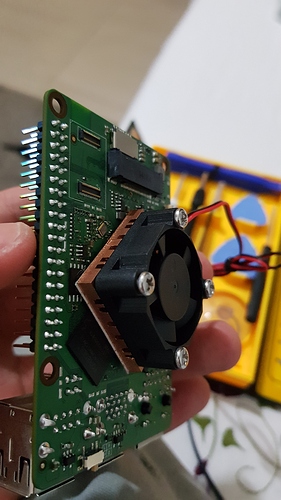
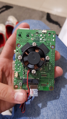
If anything, that is about the opposite from what I would expect. It should be MORE stable at lower temperatures. Suggests to me that something is being shorted out.
I don’t know the details of most of those chargers, except that most or all of them appear to contain some form of “smart” to them, which ultimately can do nothing but muck things up. Further, they are all likely to start at 5v output until they are instructed to step up the voltage.
The schematic for this board calls for 12 volt power input. 12V input runs to a pair of 5 volt buck regulators. While the datasheet for the 5 volt buck regulators isn’t explicit in this, at every instance they show an output set to 5 volt, they are showing a minimum input of 6 volt. So if you’re feeding the board with a 5 volt power supply, the output of those buck converters is probably somewhere in the range of 4-4.5 volt, which is too low. While the instruction manual may indicate that USB PD/QC/etc. adapters are compatible, the startup state in ALL of them is to output 5V. This is so as not to cause damage to devices not capable of accepting the higher voltages.
Now the board does have an LDR6015T PD controller;
That means that it is supposed to signal the power adapter to switch to a higher voltage.
HOWEVER, the functionality of this part is subject to a whole bunch of other conditions being met, none the least of which is the fact that your WIRE needs to be implemented correctly.
If it were me, what I would do, is rig up a true 12 volt 3 amp adapter, and wire it straight up to the VCC12V_DCIN contact point beside the power measurement resistor (R2).


