Fixed voltage power supply options

Since Ohm’s law is still existing this will result in massive voltage drops. How low can we go? 3V?

With 5V @ 6A at the power source you get either 5V at the PMIC or 6A but never both :slight_smile:

Asides that if all that has to be powered is ROCK 5B with RTL8125BG in 2.5GbE mode and for example a JMS585 SATA card in the M.2 slot why shouldn’t 5V @ 2.5A be fine?

1 Like

I don’t think running more than 3A on normal usb connecter is a good idea, it should be a big hidden trouble.

At least USB-C is rated for 3A but all USB PD power modes exceeding 15W are defined with higher voltages for a reason. Since the losses at 5V with higher amperages are insane.

This is an illustration how high the losses are with typical Micro USB cables.

USB-Cable-Voltage-Drop

Now imagine being at 3A or even higher with cables / PCB traces that aren’t ultra thick and super short…

so use higher voltage please. do not use 5V power supply to provide more than 15W.
btw. connector contact resistance is much more higher than wired resistance when cable length not very long.

Wow, thanks for the many and detailed answers! It is great to hear that I should be able to directly connect a 12V supply to the USB-C port.
I also thought about resistive losses and you can somewhat mitigate them by trimming the 12V supply to 12.5V or the 5V supply to 5.3V. This can give a bit more headroom.
Since I need a separate step down converter for 5V anyway (in case I were to go that route), I could put the sense connection on the second 5V and GND pin in order to fully mitigate any resistive losses. However I still feel kind of bad thinking about pushing eg. 5A through some small PCB traces.
Given the board could easily consume >30W peak with the SoC running full speed, as well as a NVMe drive, WiFi card and maybe some USB drives consuming their allowed current of up to 1A each, I am wondering whether there are some known limitations for the maximum input power via the USB-C port? The step down converter there might also have to support quite a lot of output current into the 5V rail. If the onboard converter is sufficient supplying 12.5V/3A on the USB-C port would at least be much simpler compared to 5V/6A (maybe with separate sense connections) via the GPIO headers.

Didn’t go to well with the pd I got as a boot loop like others but some new dtb’s for that, but I prefer 12v @ 12v with just a simple barrel to type C.
Always get a bit nervous for some reason putting static on type C but all is well :slight_smile:

The offending PD

I have a 12v fan there so absolutely silent, think if I hold against ear I can just make it out.

Might as well just post the sbs-bench here http://ix.io/44sB

5A 12vDC barrel

3 Likes

Just to be clear: the board is powered by 12V, no USB PD involved and sensors reports this:

tcpm_source_psy_4_0022-i2c-4-22
in0:           5.00 V  (min =  +5.00 V, max =  +5.00 V)
curr1:         1.50 A  (max =  +1.50 A)

Thank you for making that so clear :slight_smile:

Hi @stuartiannaylor
Do you happen to have access to an oscilloscope? It might be interesting to hook it up to the 12V input voltage, internal 5V and whatever other internal voltages might easily be accessible. This way it might be possible to check for voltage stability (e.g. drops and spikes) that might be indicative of issues with the onboard voltage converters.

Nope and my multimeter isn’t up to it even though samples.
I think the boot loop is just a renegotiation as haven’t bothered checking as someone posted a dtb for pd power and guess they are already ahead on that one.

Everything is really stable for me on 12v but my preference for 12v is as an additional peripheral rail as its handy.

No problem :slight_smile: worst case I could stabilize it somewhat externally via additional capacitors…
I am pretty happy already known that I can just use a single 12V supply for everything (should also help with idle current consumption).

It was meant as a question but I forgot the question mark :slight_smile:

Can you please provide output from the following while powering with ‘static 12V’:

grep "" /sys/class/typec/port0/* 2>/dev/null
cat /sys/class/typec/port0/port0-partner

grep “” /sys/class/typec/port0/* 2>/dev/null
cat /sys/class/typec/port0/port0-partner
/sys/class/typec/port0/data_role:host [device]
/sys/class/typec/port0/orientation:reverse
/sys/class/typec/port0/port_type:[dual] source sink
/sys/class/typec/port0/power_operation_mode:1.5A
/sys/class/typec/port0/power_role:source [sink]
/sys/class/typec/port0/preferred_role:sink
/sys/class/typec/port0/supported_accessory_modes:none
/sys/class/typec/port0/uevent:DEVTYPE=typec_port
/sys/class/typec/port0/uevent:TYPEC_PORT=port0
/sys/class/typec/port0/usb_power_delivery_revision:3.0
/sys/class/typec/port0/usb_typec_revision:1.2
/sys/class/typec/port0/vconn_source:no
/sys/class/typec/port0/waiting_for_supplier:0
cat: /sys/class/typec/port0/port0-partner: Is a directory

Sorry, that should’ve read cat /sys/class/typec/port0/port0-partner/supports_usb_power_delivery instead.

Thats quite a funny one

cat /sys/class/typec/port0/port0-partner/supports_usb_power_delivery
no

I think that might be output related without reading.

There is a 4.5-26v buck 5v that feeds another same buck with 4v out.

If you have PD it will negotiate but input wise it doesn’t matter as long as between 4.5v & 26v (which is confusing as referred to as a step down) it will manage 5v 8 amp if it was needed and supplied.
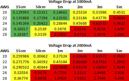
Maybe it is as Radxa have it labelled as 5.148V but 12v for volt drop, getting a 12v rail and having spare 12v barrel is useful for me.

I presume https://www.monolithicpower.com/en/mp8759.html

At a guess if you have a dumb psu none of that really has any effect on the port as its just hardwired to the buck input.
The test will see.

1 Like

Thanks for those detailed answers guys! :slight_smile:
According to the schematic it even seems to be possible to measure/monitor the input voltage directly since it is connected to SARADC_VIN6 via a voltage divider.
I am already curious about tinkering with all that low level information once the boards are broadly available!

1 Like

I have another fixed voltage power supply question:

The 5v on the board is created by the MP8759. It’s input supply can be up to 26 Volts

Can I use a 24V 2A fixed voltage power supply adapter for the rock5B? It is much easier to obtain and less expensive.

24V is too close to the voltage abs limit .
you’d better use 20V power supply to keep enough safety margin.

No. The design assume 20V is the max. 24V is strongly not suggested.

So going from a regular PSU, how would one achieve this… I’m in the same boat as the OP