Ah, I just noticed your original reply used a Waveshare PCIe to M2 Mini adapter. I’ve just ordered one so I can test. Maybe there’s a quirk in the power rail on other HATs I’ve been testing… I just have no clue why it won’t work here!
Just tried with the same Waveshare HAT you had pictured above:
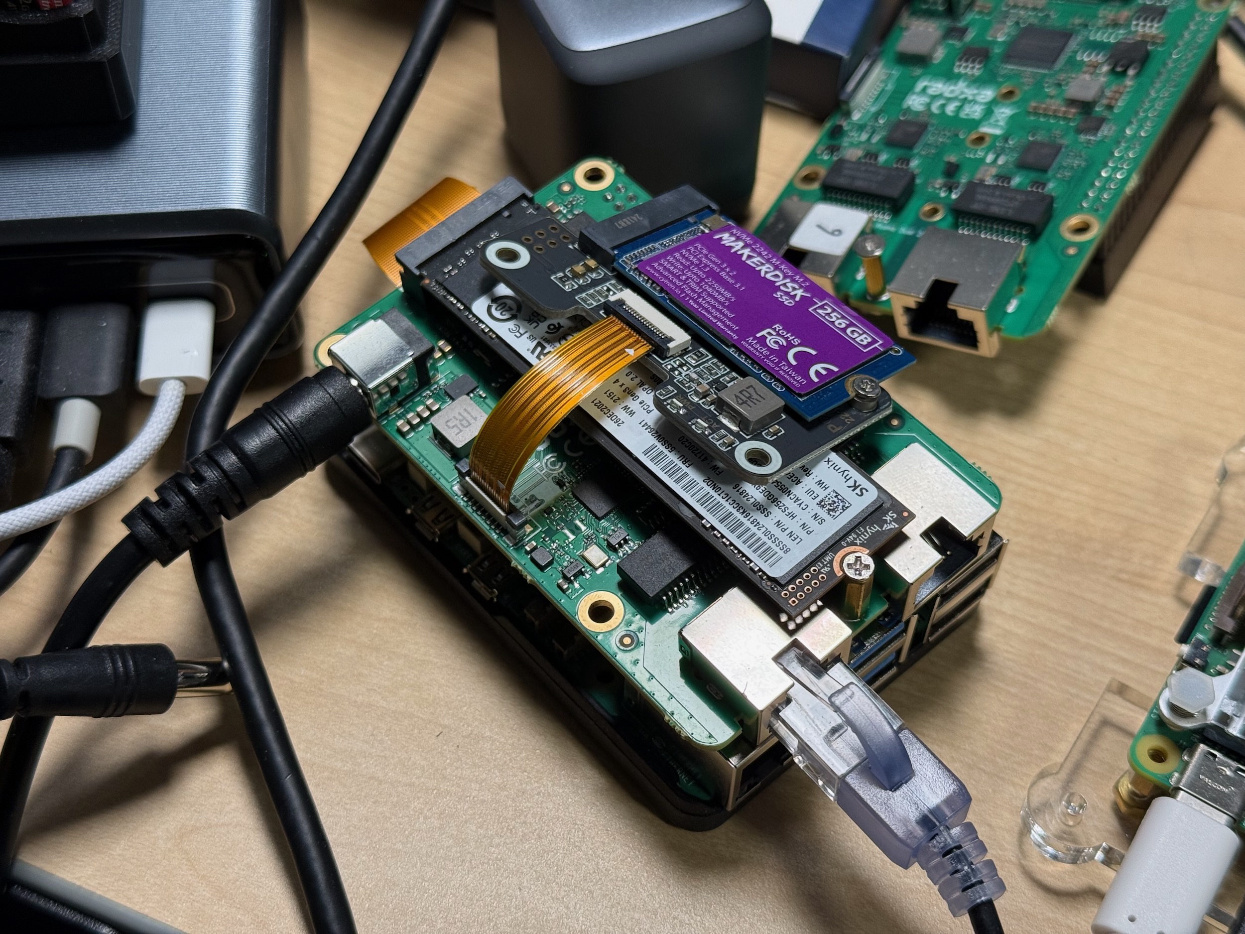
It still would not show up in lspci:
$ lspci
0000:00:00.0 PCI bridge: Broadcom Inc. and subsidiaries BCM2712 PCIe Bridge (rev 21)
0000:01:00.0 PCI bridge: ASMedia Technology Inc. ASM2806 4-Port PCIe x2 Gen3 Packet Switch (rev 01)
0000:02:00.0 PCI bridge: ASMedia Technology Inc. ASM2806 4-Port PCIe x2 Gen3 Packet Switch (rev 01)
0000:02:02.0 PCI bridge: ASMedia Technology Inc. ASM2806 4-Port PCIe x2 Gen3 Packet Switch (rev 01)
0000:02:06.0 PCI bridge: ASMedia Technology Inc. ASM2806 4-Port PCIe x2 Gen3 Packet Switch (rev 01)
0000:02:0e.0 PCI bridge: ASMedia Technology Inc. ASM2806 4-Port PCIe x2 Gen3 Packet Switch (rev 01)
0000:03:00.0 Non-Volatile memory controller: SK hynix Gold P31/PC711 NVMe Solid State Drive
0000:05:00.0 Ethernet controller: Realtek Semiconductor Co., Ltd. RTL8125 2.5GbE Controller (rev 05)
0000:06:00.0 Ethernet controller: Realtek Semiconductor Co., Ltd. RTL8125 2.5GbE Controller (rev 05)
0001:00:00.0 PCI bridge: Broadcom Inc. and subsidiaries BCM2712 PCIe Bridge (rev 21)
0001:01:00.0 Ethernet controller: Raspberry Pi Ltd RP1 PCIe 2.0 South Bridge
Is it possible it’s a power supply option? I’ve tried two different Raspberry Pis, and four different HATs now, so there’s something definitely happening that’s throwing me for a loop, haha! Maybe I’m in the middle of some strange singularity in space that’s causing PCIe signaling/power to fail.
It could be related to track length matching. I’ve experienced this already in the past. It was with the RK3399 firefly board. I had made my own PCIe adapter from a pair of connectors and perfectly adjusted copper wires that had the exact same length (differences less than 0.1mm). Some cards would work and others not. I spent a whole week-end trying to verify if I wasn’t missing anything. After some tinkering and adjusting wire lengths I got another card to work. I finally gave up and found their official mezzanine board for sale on ebay, so I ordered it. When I received it, it was the exact opposite: the boards that used not to work with my adapter did work, and those which previously did were not recognized anymore! The only one that did was the last one which started working late, making me think it was probably tuned between the two! I verified everything and both of our cabling were exactly the same.
Thus what you’re facing here really makes me think about that. It’s probably a combination of line capacitance (caused by connectors) and track length which might not be perfectly matched. I was already facing problems with Gen2, here you’re on Gen3 which might be even more sensitive.
It could be completely unrelated, of course, but I thought I should share this experience since what you’re facing looks pretty similar.
Hi @geerlingguy
Are the cables on this side connected in the right direction? Can you post a separate picture of the FPC cable you are using?
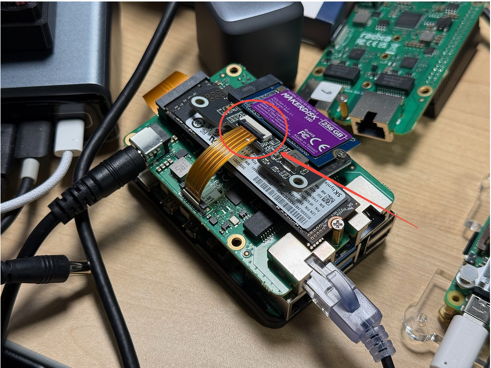
Ah! Finally I have it working:
$ lspci
0000:00:00.0 PCI bridge: Broadcom Inc. and subsidiaries BCM2712 PCIe Bridge (rev 21)
0000:01:00.0 PCI bridge: ASMedia Technology Inc. ASM2806 4-Port PCIe x2 Gen3 Packet Switch (rev 01)
0000:02:00.0 PCI bridge: ASMedia Technology Inc. ASM2806 4-Port PCIe x2 Gen3 Packet Switch (rev 01)
0000:02:02.0 PCI bridge: ASMedia Technology Inc. ASM2806 4-Port PCIe x2 Gen3 Packet Switch (rev 01)
0000:02:06.0 PCI bridge: ASMedia Technology Inc. ASM2806 4-Port PCIe x2 Gen3 Packet Switch (rev 01)
0000:02:0e.0 PCI bridge: ASMedia Technology Inc. ASM2806 4-Port PCIe x2 Gen3 Packet Switch (rev 01)
0000:03:00.0 Non-Volatile memory controller: SK hynix Gold P31/PC711 NVMe Solid State Drive
0000:04:00.0 Non-Volatile memory controller: Phison Electronics Corporation PS5013 E13 NVMe Controller (rev 01)
0000:05:00.0 Ethernet controller: Realtek Semiconductor Co., Ltd. RTL8125 2.5GbE Controller (rev 05)
0000:06:00.0 Ethernet controller: Realtek Semiconductor Co., Ltd. RTL8125 2.5GbE Controller (rev 05)
0001:00:00.0 PCI bridge: Broadcom Inc. and subsidiaries BCM2712 PCIe Bridge (rev 21)
0001:01:00.0 Ethernet controller: Raspberry Pi Ltd RP1 PCIe 2.0 South Bridge
I flipped the cable around, a 180, and it is giving me the power LED and the NVMe drive is recognized.
I mounted the NVMe drive, and ran a disk benchmark to be sure I was getting full bandwidth:
| Benchmark | Result |
|---|---|
| iozone 4K random read | 51.61 MB/s |
| iozone 4K random write | 184.09 MB/s |
| iozone 1M random read | 659.47 MB/s |
| iozone 1M random write | 707.95 MB/s |
| iozone 1M sequential read | 669.09 MB/s |
| iozone 1M sequential write | 697.44 MB/s |
So it seems the mystery is solved!
Well the M.2 HAT worked, but it seems like the other HATs still don’t, re-confirming the orientation is correct on the HAT side; I unplugged the FFC from a Pi 5 that was confirmed working, and plugged it directly into the Router HAT, and I’m not seeing PWR light up on the HAT+ HAT, nor anything with lspci.
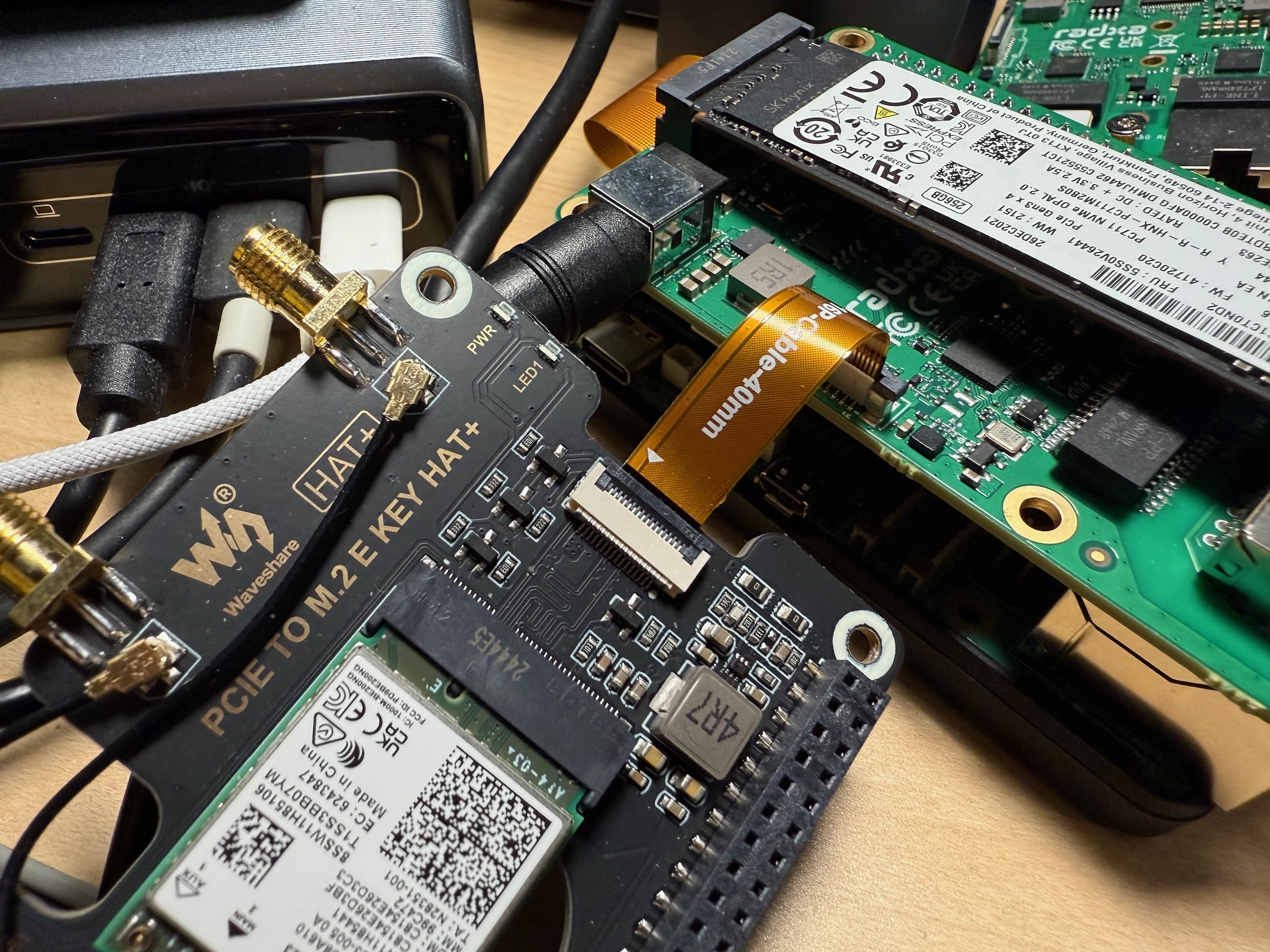
On the regular Pi 5, the PWR LED lights up immediately when I power on the Pi 5. I am not using any GPIO pins on the Pi 5 either, so the setup should be identical.
I’ve re-seated the cable two times (on both sides), and still no PWR LED on the WiFi HAT+.
Hi @Mitchell , I followed the instruction for correct usage of the FFC connector with the exact same PCIe to M.2 Waveshare board, but I could not get it working. Could you please suggest me troubleshooting steps?
I got the Radxa dual 2.5G router hat v1.5. Is something has changed in this version?
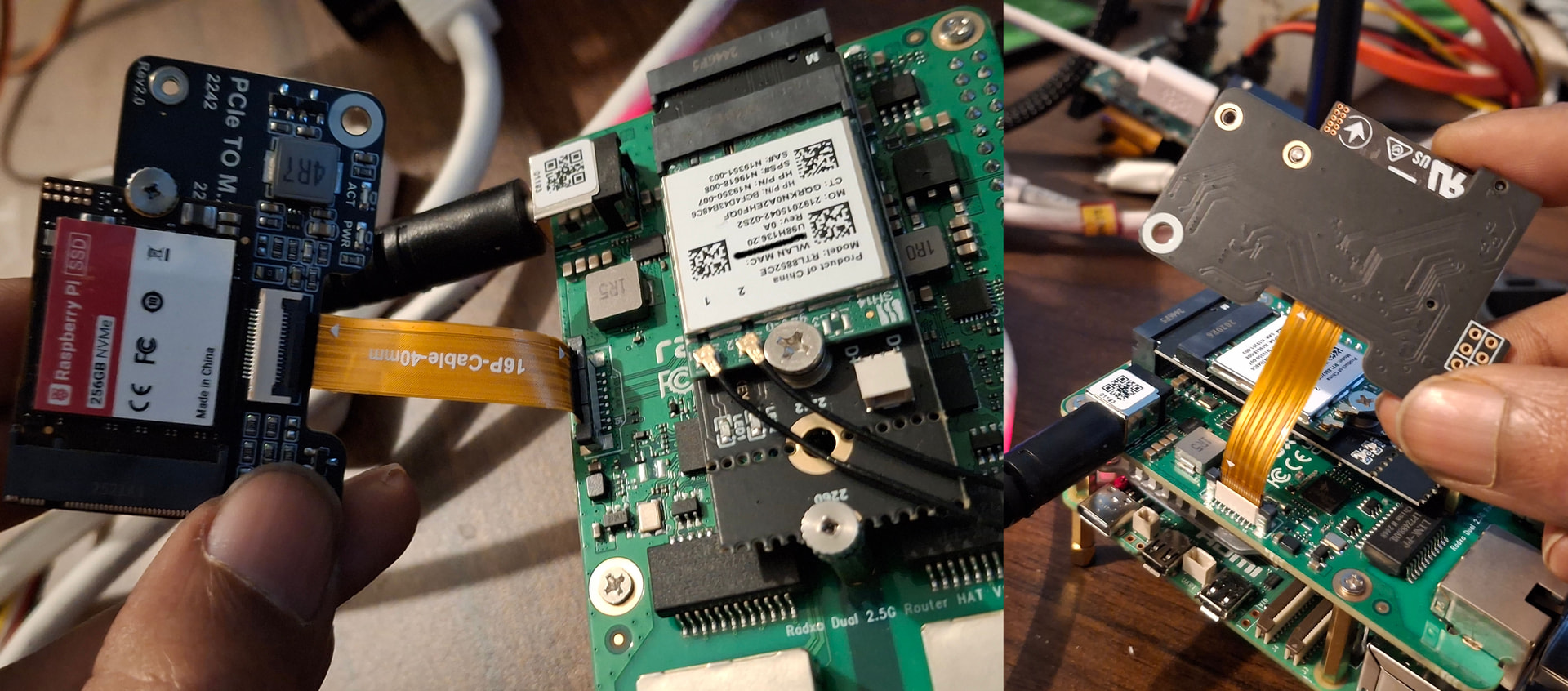
PS: I made another post since I didn’t notice that an instruction has already been provided in this thread.
Could this be an issue with the power-up sequence? I notice that the FPC power supply for this expansion board is controlled by the GPIO16 pin, yet the device tree configurations for the official Radxa, Armbian, and OpenWrt systems do not contain detailed control settings for this GPIO.
I’ve pulled up the GPIO P16 in my OpenWRT system, and now the PWR LED on my ASM1182E expansion board is lit, and the chip is recognized in the system. I’ll modify the device tree and recompile the firmware to enable the pull-up during the PCIe enumeration phase to see if that works.
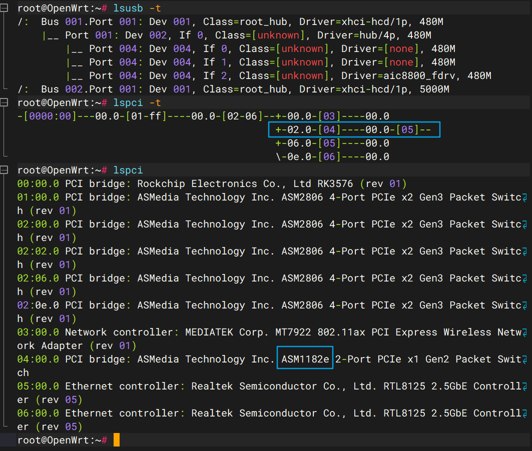
I’ve confirmed the root cause and the issue is now solved.
On the ROCK 4D, physical pin 16 is
GPIO2_B6. With the default OpenWrt device tree, this GPIO stayed as an input/LOW. I measured:40-pin GPIO16: 0 V FPC pin 13 (POWER_EN): 0 VWhen I manually drove GPIO16 HIGH from userspace:
gpioset -c gpiochip2 14=1both GPIO16 and FPC pin 13 changed to about 3.3 V, the PWR LED on the ASM1182E board turned on, and the ASM1182E immediately appeared in
lspci:04:00.0 PCI bridge: ASMedia Technology Inc. ASM1182e 2-Port PCIe x1 Gen2 Packet SwitchHowever, the NVMe behind the ASM1182E was still missing. This turned out to be a second issue caused by enabling the switch too late. During the initial PCIe enumeration, the ASM2806 FPC port was empty, so Linux assigned only bus 04 to that downstream bridge:
primary=02, secondary=04, subordinate=04After enabling the ASM1182E from userspace, it needed additional PCI bus numbers for its own downstream bridges, but buses 05 and 06 had already been assigned to the two RTL8125 ports. The kernel reported:
pci 0000:04:00.0: devices behind bridge are unusable because [bus 05] cannot be assigned for them
pcieport 0000:02:02.0: bridge has subordinate 04 but max busn 05
I then modified the ROCK 4D device tree so
GPIO2_B6is driven HIGH before the PCIe enumeration starts, for example using a GPIO hog:&gpio2 { router_hat_pcie_enable { gpio-hog; gpios = <RK_PB6 GPIO_ACTIVE_HIGH>; output-high; line-name = "router-hat-pcie-enable"; }; };After rebuilding OpenWrt and doing a cold boot, the whole PCIe topology enumerates correctly, including the ASM1182E downstream ports and the NVMe SSD.
So in my case, the FPC link itself and the ASM1182E were fine. The real problem was that GPIO16/FPC
POWER_ENwas not asserted early enough. A simple NVMe adapter may still work because it may not depend on thisPOWER_ENsignal in the same way, while my ASM1182E expansion board does.It may be worth adding an appropriate GPIO16 configuration to the official ROCK 4D device tree or documenting this requirement for the Dual 2.5G Router HAT.
Hi! Thanks for raising this topic again. I have the same issue with the hat on a raspberry pi 5. Can you please detail exactly what you have done to rectify the issue?
I have driven gpio23 output high (I have tried with both a dt overlay and a config.txt entry) and now get power to a waveshare m.2 adapter (the same as used above) but still no joy with getting any pcie devices to be recognised on the FPC connector. The kernel reports a pcie error relating to the FPC connected device (I have tried three different devices), the error does not change regardless of the device. The dmesg log below is with a samsung nvme drive that I have previously used as a boot device on the same pi;
The switch chip is seeing the device, downgrading the link and still not enumerating.
[ 0.506151] pci 0001:02:02.0: broken device, retraining non-functional downstream link at 2.5GT/s
[ 0.522933] pci 0001:02:02.0: removing 2.5GT/s downstream link speed restriction
Followed by the device itself:
[ 1.175095] pci 0001:04:00.0: [144d:a809] type 7f class 0xffffff conventional PCI
[ 1.777277] pci 0001:04:00.0: unknown header type 7f, ignoring device
[ 1.801172] pci_bus 0001:04: busn_res: [bus 04-ff] end is updated to 04
The kernel is explicitly flagging that port’s link as broken and force-retraining it down to the lowest possible speed just to get any link at all but is unsuccessful.
I have tried many overlays including:
dtoverlay=pciex1-compat-pi5,no-mip
dtoverlay=pcie-32bit-dma-pi5
I have disabled ASPM via pcie_aspm=off to /boot/firmware/cmdline.txt
Nothing works for me. The other devices all work fine but not the FPC.
In my case, the fix was to assert the HAT’s PCIe/FPC enable GPIO before the first PCIe enumeration, rather than enabling it later from userspace.
On the ROCK 4D, physical pin 16 is GPIO2_B6. I first verified the relationship manually:
gpioset -c gpiochip2 14=1
This changed:
40-pin pin 16: 0 V -> 3.3 V
FPC pin 13:    0 V -> 3.3 V
The PWR LED on my ASM1182E expansion board then turned on, and the ASM1182E immediately appeared in lspci.
I then changed the ROCK 4D device tree so this GPIO is driven HIGH during early boot:
&gpio2 {
    router_hat_pcie_enable_hog: router-hat-pcie-enable-hog {
        gpio-hog;
        gpios = <RK_PB6 GPIO_ACTIVE_HIGH>;
        output-high;
        line-name = "router-hat-pcie-enable";
    };
};
After rebuilding OpenWrt and doing a cold boot, the ASM1182E was already powered when Linux performed the initial PCIe scan. Linux could then allocate the additional bus numbers required by the cascaded PCIe switch, and the NVMe behind the ASM1182E enumerated correctly as well.
I documented the full investigation and the relevant changes here:
https://github.com/ovo-ukiyo/openwrt/tree/rock-4d-aic8800-router-hat
The most relevant notes are in:
docs/rock-4d-aic8800-router-hat.md
Your Raspberry Pi 5 case looks slightly different from mine, though. Since you are already seeing the Samsung device ID:
[144d:a809]
but then getting:
type 7f
class 0xffffff
the downstream device is at least powered and partially communicating over PCIe. That looks more like a PCIe link/config-space stability issue than the pure POWER_EN problem I had.
I would first verify that GPIO23 is already HIGH before PCIe enumeration, and then focus on:
- FFC orientation and cable/contact quality
- power supply stability
- PCIe link stability / Gen1 vs Gen2 behavior
- REFCLK / PERST# timing
The DMA/MSI overlays are probably not the main issue at this stage, because enumeration is already failing while Linux is reading the PCI configuration space.
If you use Codex, you can also point it directly at my branch and ask it to compare the ROCK 4D fix against the Raspberry Pi 5 boot/device-tree setup, inspect the PCIe logs, and prepare a Pi 5-specific overlay or patch automatically. That may be the quickest way to narrow down whether your GPIO23 timing is actually equivalent to the early-boot enable I used.